Loading... Please wait...
- Home
- Trucking Directories
-
Truckers News Feed
- Semi Truck Accidents News Reports
- Bus Accidents News Reports
- Current USA Diesel Fuel Prices
- Take Our Border Back Convoy News Coverage Live Streams Schedule Route Activities
- USA Real Time Road Conditions
- FMCSA DOT CDL News Regulations Enforcement Actions
- Trucking Companies Driver Scams Ripoffs Hiring Training Leasing
-
Video Library
- EXTREME Big Rig Truck Wrecks Crashes Accidents Videos
- Custom Big Rig Semi Truck Videos
- Tutorial Video National Registry Medical Examiner
- Big Rig Trucker Training Videos
- Heavy Haul Trucking Big Rig Videos
- FasterTrucks Road Train Videos
- Perils of Speed Limiters in Big Rig Trucks Videos
- Global Truckers Videos
-
Articles
- Top 50 Tips Every Truck Driver Should Know
- Truck Driver Safe Driving Rules
- Downsides of Driving a Truck in Winter
- How to Find a Truck Driving School
- Top 5 Characteristics Successful Truck Drivers
- Truck Driver Accident Procedures
- Owner Operator Tax Deductions
- DOT CDL Commercial Vehicle Inspection Procedures
- HOS New Hours of Service Rules FAQ Truckers
- SafetyPass Pro
- Search Trucking
- Contact Us

Videos How To Chain Up Big Trucks Tire Chains Instructions
Videos - Learn How To Chain Up a Big Rig Semi Truck or 18 Wheeler. Experienced Truck Drivers Show You How to do it. Single Tire Chains and Double Tire Chains (Three-Railers) Installation Instructions.
- Home
- SafetyPass Pro
- Installation Guide
Installation Guide
How to Install the SafetyPass Pro

SafetyPass Pro Cable Installation Video
Installation Kit fits most brands of trucks, including Freightliner, Kenworth, Peterbilt, Sterling, Western Star Volvo and others with Weather-Pack or Metri-Pack connectors.
Step 1 - Connector Identification and Location...
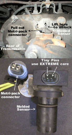
Locate the vehicle speed sensor (VSS) at the rear of the transmission, just in front of the U-Joint and drive shaft. Metripack connectors are found on most newer trucks after 2001. Pre 2002 trucks use Weatherpack connectors as seen below.
After locating the speed sensor at the rear of the transmission on the output shaft. Unplug the connector from the top of the molded speed sensor.
Using your thumb or index finger, gently lift up on the retaining clip and pull the Metri-Pack plug from the top of the sensor housing.
Use the Metripack adapter cable that came with your kit. Plugin the connector that came from you speed sensor to the mating adapter cable connector. Use the other metripack adapter cable and plug it into the top of the speed sensor. Plug in the other ends of adapter cables to mates on the Main Cable.
SafetyPass Pro XM7KT
Caution: The metal pins in the speed sensor housing are very fragile. Be sure to index the metal pins properly before applying pressure to seat the connector. Match up the mating connectors and apply pressure. You will hear a distinctive clicking sound as the connectors lock in to place.
To hook up to WeatherPack Connectors, mostly found on pre-2001 vehicles. Locate the speed sensor at the rear of the transmission on on the output shaft. Follow the wires from the speed sensor, normally to the top of the transmission to locate the in-line connectors.
 Weatherpack inline connectors are black in color with green cable seals. Occasionally different colored seals may be used.
Weather-Pack Connectors always have round, metal, male and female pins inserted into a plastic housing.
Separate the connectors by using your thumb to lift the retaining clip and then pull the connectors apart.
Connect the Inline connectors to the Main Cable that came with your kit.
Two Lead or Two Sensor Installation Instructions:
Some older model trucks 1992-2006 may have more than one set of leads coming from the speed sensor or they may have two separate speed sensors.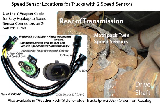
If this is the case, the first set of leads (two wires) will be for the speedometer and the second set will go to the truck computer (ECM). This is also true if you have two separate sensors.
On some trucks the second set of leads are actually “dummy leads” that dead-end at the Weather-Pack connectors. In this event you should follow the normal installation instructions outlined previously that apply to all "one sensor" trucks.
Use the Y Adapter Cable to connect to speedometer and ECM simultaneously. Begin installation by unplugging both speed sensor connectors. Plug the ECM leads into the mating Y adapter connectors, then plug-in other end of Y Adapter to the main cable. Attach other side of main cable to ONE speed sensor only. Use single adapter lead if necessary. The other speed sensor may be removed as a spare or left in place.
Step 2 Route Main Cable to cab Interior...
Route the Main Cable (RCA Jacks) to the cab interior.
Permanent" or "Temporary" installation?
If you are performing a permanent installation you can use cable ties to attach the Main Cable to the existing wire harness and enter the cab through the firewall.
When installing on a temporary basis, the installation wire harness can be routed into the cab by running it through one of the door openings. Make sure the wire harness is on the soft part of the door gasket and NOT in an area where metal touches metal, i.e. Door latch, hinges, alignment plate, etc.
Entry to the cab can also be made through the the sleeper floor.
Always be sure to secure loose wiring using the included cable ties that came with your installation kit. This will insure protection from moving parts located under the vehicle i.e. driveshaft, etc.
Sleeper doors are also an option. Avoid routing near extreme heat sources such as exhaust piping. Once familiar with temporary installation, 5 minute removal and installation will become common practice.
Step 3 - Install the Control Unit
The Control unit has been designed to fit into a standard cup holder located near the dash board within easy reach of the driver.
Optionally it can be placed anywhere in the cab within 3' of a 12 volt power receptacle.
Plug in the control unit to the Main Cable using the mating RCA connectors. Plug in the DC power connector to the corresponding hole on the back of the control unit and finally to the cigar lighter plug.
Be sure to read operating instructions carefully prior to using the device.
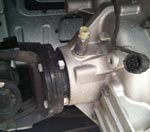 The German ZF Transmission has a circular 4-pin speed sensor connector at the rear of the transmission.
This connector has 3 or 4 wires connected to it. We do not have a mating connector to plug into it. So, the only way is to splice into one wire from your system.